

3 Years Warranty
3 Years Warranty
3 Years Warranty
3 Years Warranty


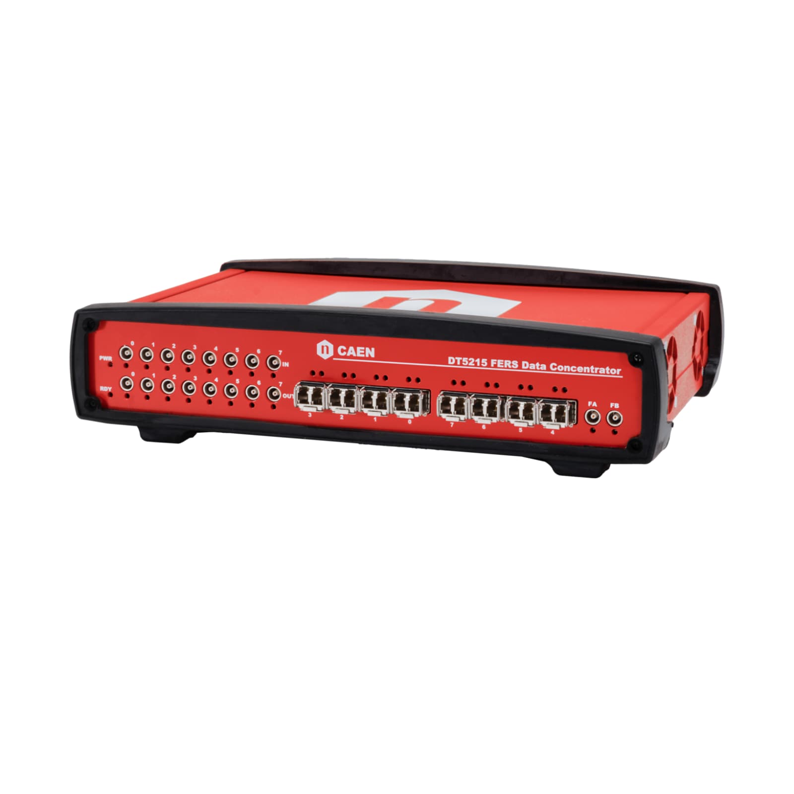
Concentrator Board for FERS-5200
FERS-5200 is a Front-End Readout System designed for large detector arrays, such as SiPMs, multi-anode PMTs, Silicon Strip detectors, Wire Chambers, GEM, Gas Tubes and others.
FERS is a distributed and easy-scalable platform, where each unit is a small card that houses 32 or 64 channels with Front End electronics, A/D converters, trigger logic, synchronization, local memory and readout interface.
FERS is a flexible platform: keeping the same readout and control infrastructure, that is the same user interface, different types of front-end can be developed to fit a variety of detectors. In most cases, the front-end is based on ASIC chips that allow for high density, cost-effective integration of multi-channel readout electronics into small size and low power modules. The Front End ASIC can implement an analog chain made of preamplifier, shaper, peak sensing and discriminator. In other cases, the ASIC is a fast flash ADC (1 GS/s or more) that records the waveform of the input pulses and makes it possible to apply digital algorithms providing timing, energy and pulse shape information.
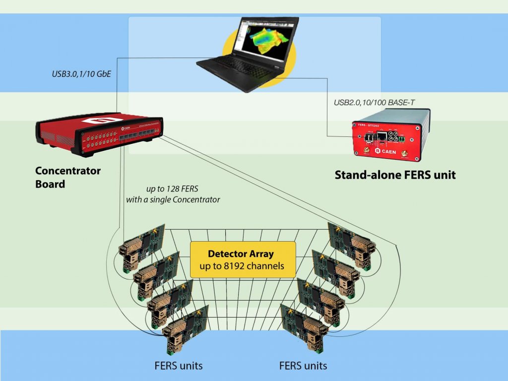
One FERS unit can be used stand alone, without any additional hardware, just connected to the computer via USB 2.0 or Ethernet 10/100T. This is a cheap and an easy-to-use evaluation board of the specific ASIC chip housed on the FERS unit. Once the solution is validated, scaling up to thousands channels is immediate: multiple FERS units can be connected in a tree network, where the optical TDlink is the unique physical connection that guarantees high throughput data readout, slow control and accurate timing synchronization.
One DT5215 (FERS Data Concentrator) can manage up to 8 TDlinks, each connected to 16 FERS units in daisy chain: in the case of the A5202/A5203 FERS unit, it makes 8192 readout channels. Multiple concentrator boards can be synchronized in order to further extend the total number of channels.
A Linux-based Single Board Computer is embedded in the Concentrator board. It manages the data readout from the network of FERS units and the event data building according to the time stamp and/or trigger ID of the event fragments acquired by each unit. Sorted and merged data packets are then stored to the local memory and finally sent to the host computers through 1/10 Gb Ethernet connection or USB 3.0 link. Custom algorithms for data processing and reduction can be easily uploaded by the user into the embedded CPU.
FERS-5200 is an extendable system: the same FERS unit can be used either as stand-alone or as part of the network tree for the readout of large arrays of detectors. In this way, the same card and same interface will be used, starting from the prototyping phase till the final implementation of the experiment.
The core of the scalability of the FERS-5200 is the optical TDlink, which manages data stream, slow control and synchronization at once.
The concentrator board DT5215 hosts 8 optical links, each one sustaining up to 16 FERS units in daisy chain. In the case of A5202 for SiPM readout, this means 8192 channels managed by a single Concentrator board.
Further scalability is possible synchronizing more than one Concentrator board.
Dimensions: 262 W × 66.2 H × 171.6 L mm3 (without connectors)
Weight: 1210 g
8 Small Form Factor Pluggable (SFP+) transceiver components for optical connection (3.125 Gbit/s).
TDlink CAEN proprietary protocol allows for multi-board synchronization, slow control and data readout
FI
| FO
| FA/FB 2 digital Input/Output LEMO connectors:
|
| RA/RB 2 digital Input/Output LEMO connectors:
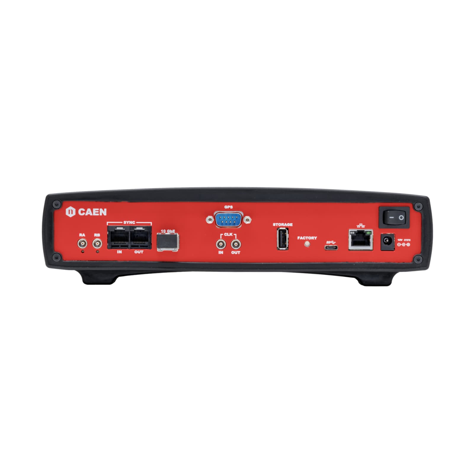
| CLK‐IN/OUT Input/Output LEMO connectors for the clock signal propagation:
| SYNC IN/OUT 2 RJ‐45 connectors for the transmission of the clock/sync signal in case of multi‐boards synchronization |
| Clock Propagation Via the TDlink:
| Acquisition Synchronization Sync signal propagated through the TDlink for simultaneous reset of the timestamps. Broadcast commands executed at the same time in all boards for Run Start/Stop, Trigger, etc. NOTE: After the synchronization command, a fixed clock skew of less than 1 clock cycle (6.4 ns) is present between the first group of four TDlinks 0‐1‐2‐3 and the second group, 4‐5‐6‐7. The clock skew may vary from run to run. |
Clock Propagation
The SYNC A clock signal can be propagated (OUTPUT ONLY) via the front/rear panel I/Os | Acquisition Synchronization Timestamp reset and Run Start/Stop through:
|
Ethernet
USB
Firmware can be upgraded via USB or Ethernet through the Web Interface
Fully controlled by the Janus software on Windows ® and Linux ®
Environment: Indoor use
Operating Temperature: 0◦C to +40◦C
Storage Temperature: –10◦C to +60◦C
Operating Humidity: 10% to 90% RH non condensing
Storage Humidity: 5% to 90% RH non condensing
Altitude: < 2000m
Pollution Degree: 2
Overvoltage Category: II
EMC Environment: Commercial and light industrial
IP Degree: IPX0 Enclosure, not for wet location
EMC: CE 2014/30/EU Electromagnetic compatibility Directive
Safety: CE 2014/35/EU Low Voltage Directive
Single power supply: +12 V. Accepted voltage range: MIN +7 V, MAX +15 V
750 mA @ +12 V, i.e. ≈ 9 W
Compare with FERS-concentrators.
Loading...
| Code | Description |
|---|---|
| WDT5215XAAAA | DT5215 - Concentrator Board for FERS-5200 RoHS |
FERS Data Concentrator with 1 optical link
64 Channel Radioroc unit for FERS-5200
Desktop 64 Channel picoTDC unit for FERS-5200
Desktop 64 Channel Citiroc unit for FERS-5200
Scientific instrumentation SiPM read-out chip
64 Channel Radioroc unit for FERS-5200
64/128 Channel picoTDC unit for FERS-5200
64 Channel Citiroc unit for FERS-5200
FERS-5200 DAQ SOFTWARE
High level library for FERS-5200 Boards
+39 0584 388 398
Contacts
What are you looking for?
Search