-
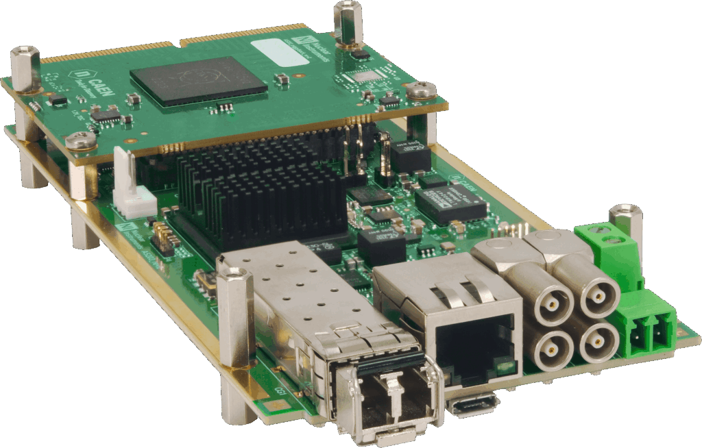
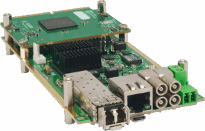
64/128-ch TDC unit for high-resolution timing applications housing the CERN picoTDC
-
Part of FERS-5200, the CAEN platform for the readout of large arrays of detectors (SiPM, MA-PMTs, Gas Tubes, Si detectors, …)
-
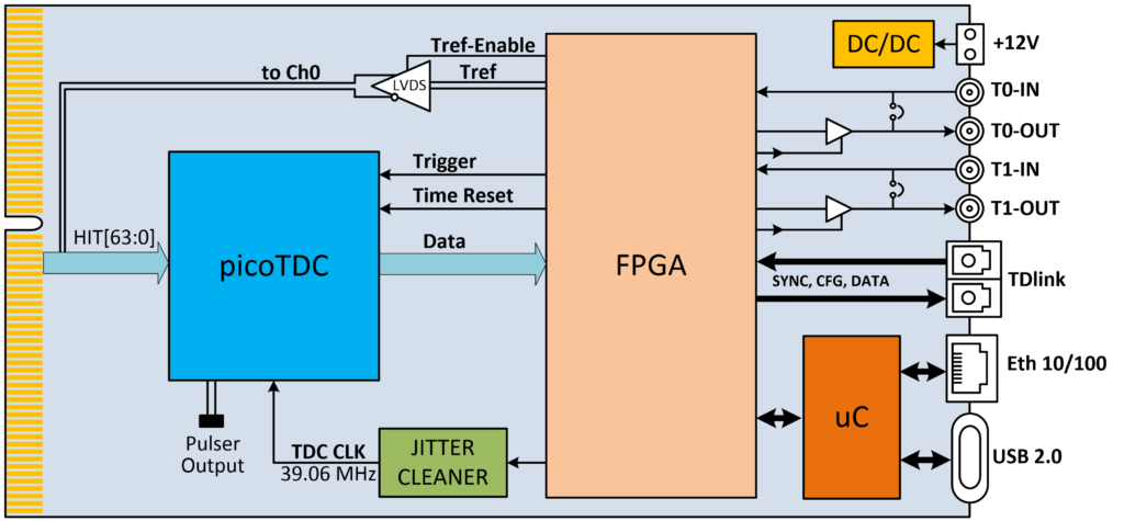
Timing resolution: LSB = 3.125 ps, RMS typ. ∼ 7 ps
-
TDC dynamic range: up to 26 bit (∼ 210 μs). Extendable to 56 bit in the FPGA
-
Inputs: differential LVDS signals (max common mode = 1.2 V; max absolute voltage = 1.45 V). NIM, TTL or analog signals through dedicated adapters.
-
Acquisition of leading/trailing edge Time of Arrival (ToA), or leading edge ToA plus Time over Threshold (ToT) of the input signals
-
Scalability and easy-synch: up to 128 cards (8192/16384 channels) can be managed and synchronized by a single DT5215 Concentrator Board, thanks to the optical TDlink
-
Janus 5203 open source software available for board configuration and DAQ control
-
Flexibility: a full range of accessories for different kind of applications
-
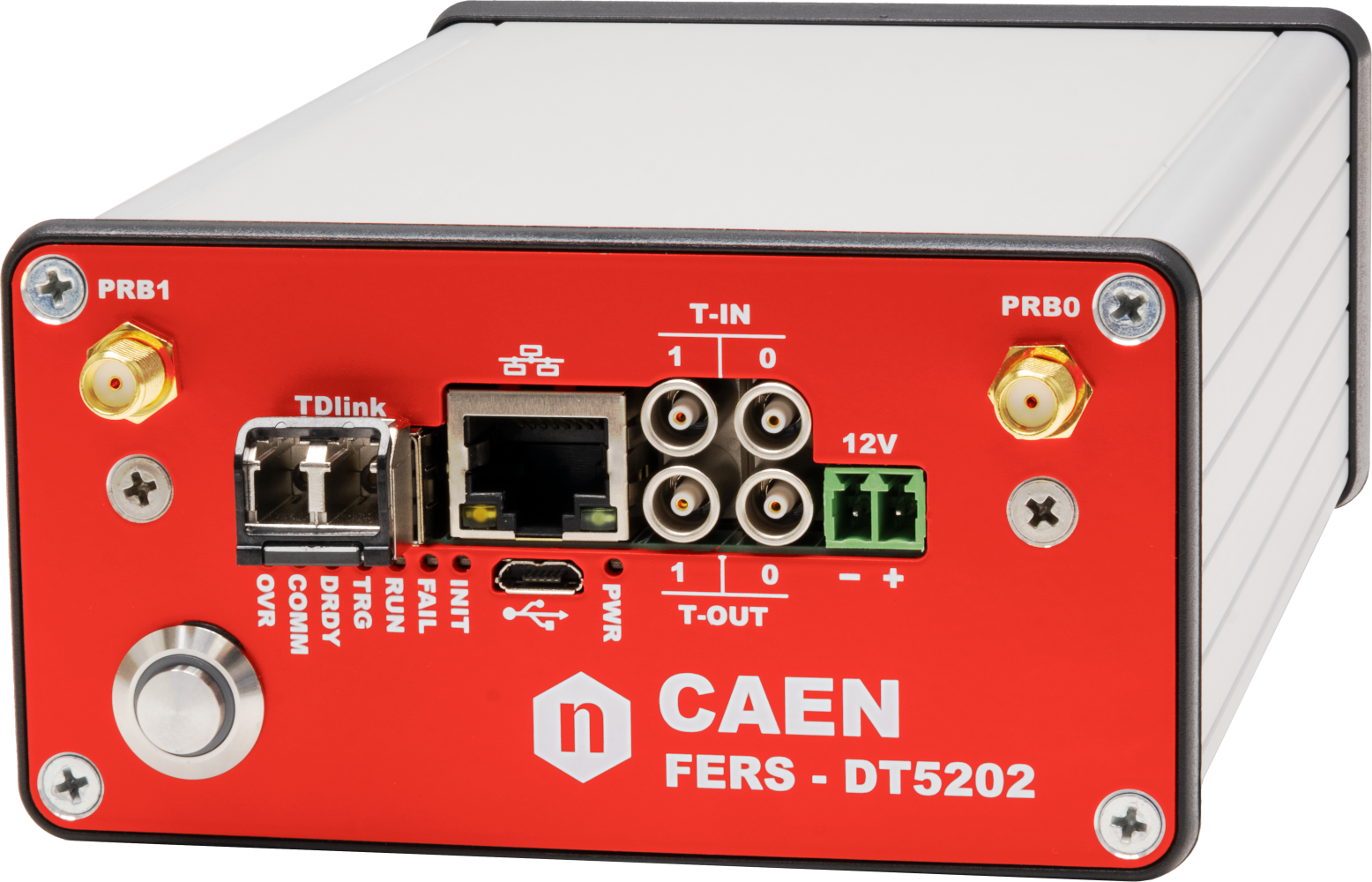
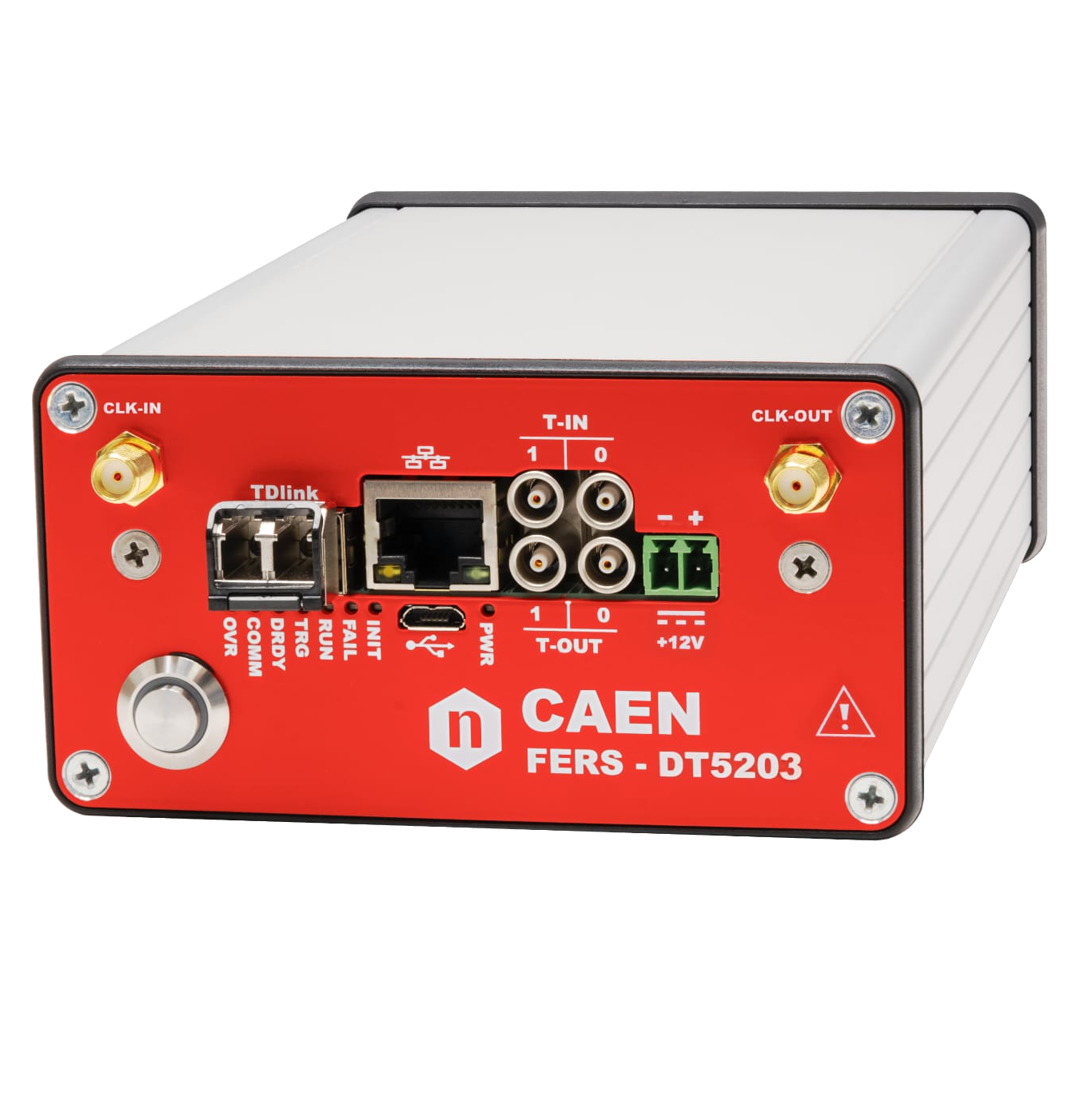
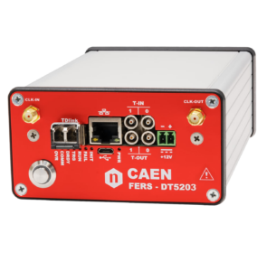
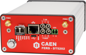
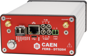
Boxed FERS unit (DT5203) for desktop use available – 64 channels only
FERS-5200 is a front‐end readout system designed for the readout of large detector arrays, such as SiPMs, multi‐anode PMTs, Silicon Strip detectors, Wire Chambers, GEMs, Gas Tubes and others. FERS‐5200 is a distributed and scalable system, where each unit is a small card that houses 64 or 128 channels. It features a detector specific Front-End interfaced to a common infrastructure that guarantees readout interfaces, slow control and synchronization. Typically, the front-end is based on ASIC chips that allow for high density, cost effective integration of multi-channel readout electronics into small size and low power modules. FERS is a flexible platform: combining the same back-end (i.e. readout architecture and interface) with different types of front-end to fit a wide range of detectors.
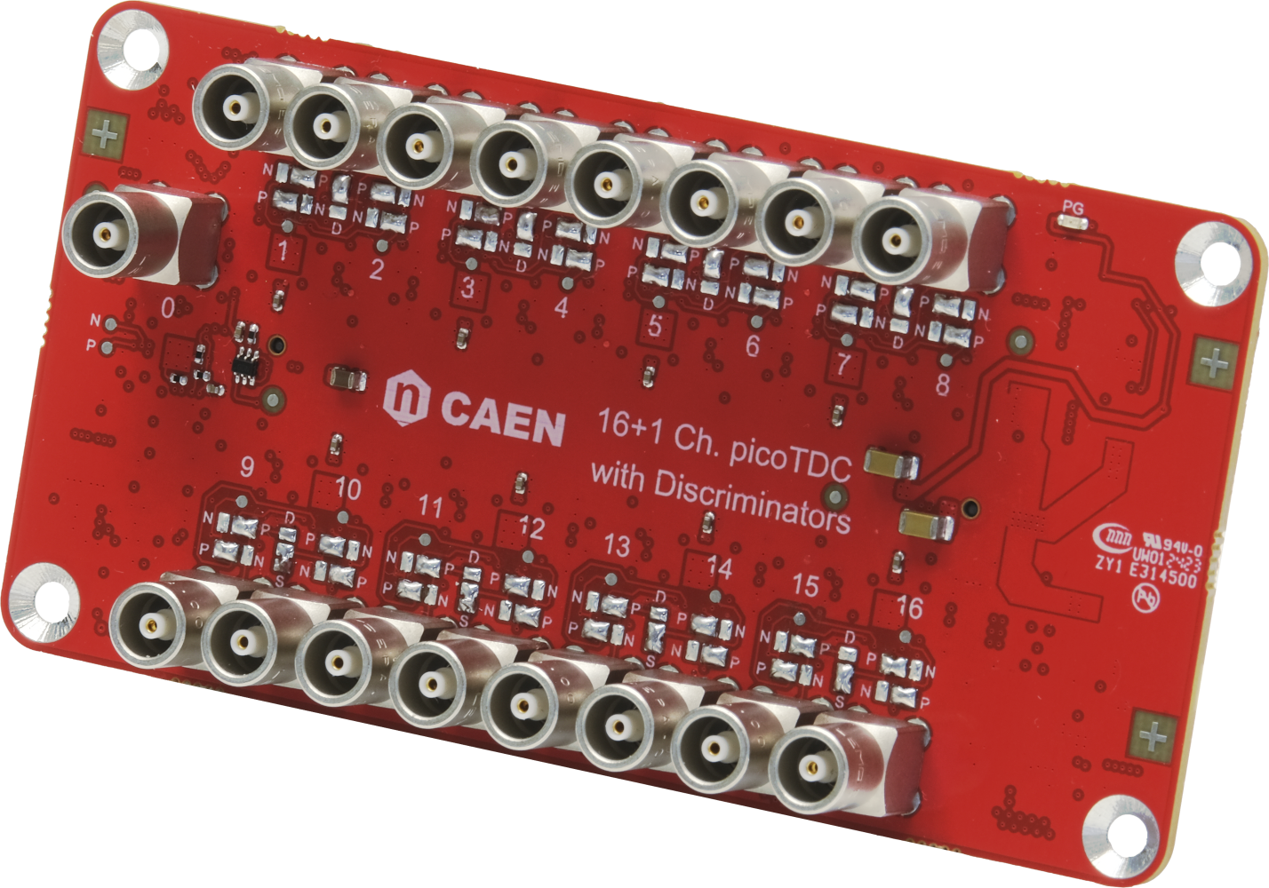
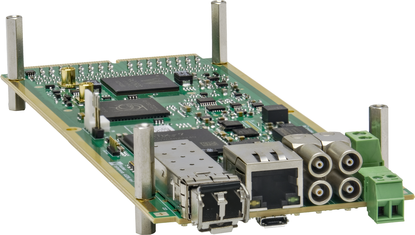
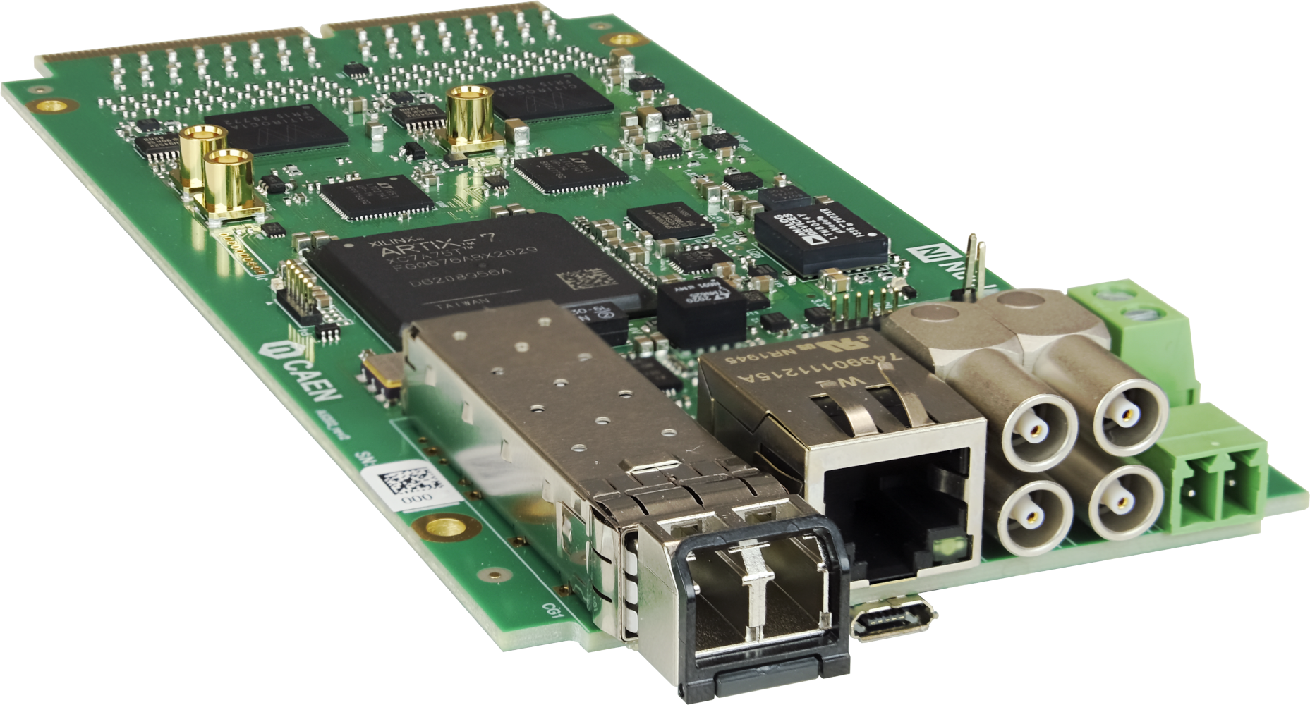
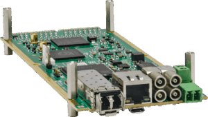
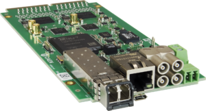
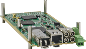
The A5203 (and DT5203, which is the boxed version for desktop use), part of the FERS-5200 family, is a Time-to-Digital Converter for high-resolution multi-hit time measurements that bases its functionality on the picoTDC chip (produced by CERN). The A5203B houses an additional mezzanine card with a second picoTDC chip, thus implementing a 128 channel TDC module.
Each readout channel accepts LVDS signals and measures the time stamp of both rising and falling edges with an LSB of 3.125 ps. In this way, the unit is able to reconstruct Time of Arrival (ToA) of signals as an absolute timestamp or as a ΔT with respect to a common Tref pulse. The picoTDC can also acquire Time over Threshold (ToT) information and combine it with the edge time stamp. The ToT allows for amplitude estimation, energy spectrum reconstruction, and timing walk correction. The latter permits to achieve optimal timing resolution with no need of Constant Fraction Discriminators.
The A5203 supports Common Start, Common Stop, Trigger Matching and Streaming acquisition modes. Have a look at FAQ for more details.
For small setups a single A5203 unit can be used stand alone, without any additional hardware, by simply connecting the unit to a PC via USB 2.0 or Ethernet 10/100T. For large readout systems, a flexible and scalable network of units can be created by means of the high speed optical link called TDlink that allows up to 16 FERS‐5200 units to be connected in daisy chain (ring) providing data readout, synchronization between the units and broadcasting of commands (e.g. start/stop run, time resets, etc.). The DT5215 is a data collector board (FERS‐CB) housing 8 TDlink masters that will make it possible to manage up to 128 FERS‐5200 units.
The A5203 is fully supported by the CAEN Janus 5203 Open Source software on Windows® and Linux®. Janus can run in console mode (C program, without graphics) or connected to a GUI written in Python. The GUI has configuration and run control panels that simplify the data acquisition management. Both console and GUI modes permits to acquire data from multiple boards, manage the event building and timing histograms (ToA and/or ToT), display data statistics (hit rate, throughput, etc…), plot histograms, and save output, including spectra and list files with the acquired timing data.
In addition, the A5203 is supported by the following third-party software:
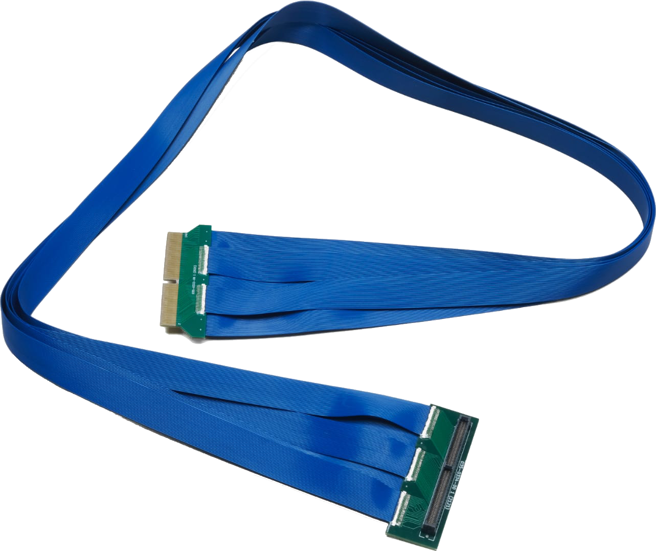
A wide range of adapters and cables has been also specifically designed for FERS-5200 boards, in order to provide versatility of choice and the ability to remotely operate the detectors, a complete list is available here.


You also may be interested in…
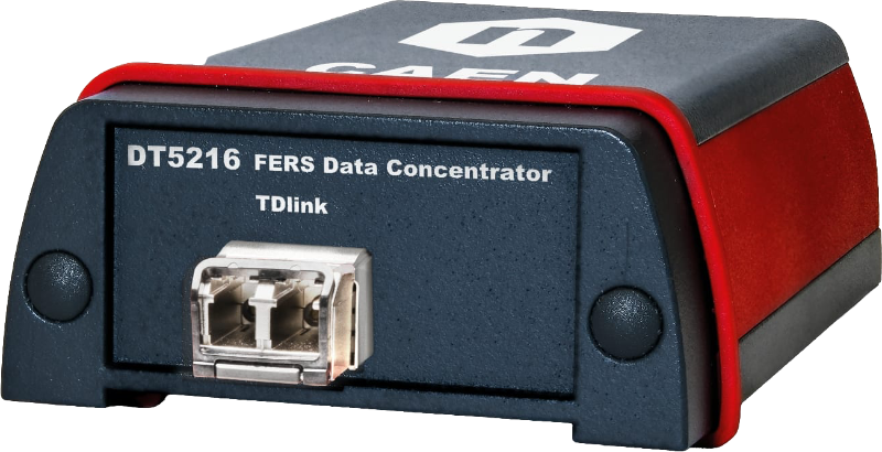
DT5216
A5204
A5202
DT5202
DT5203
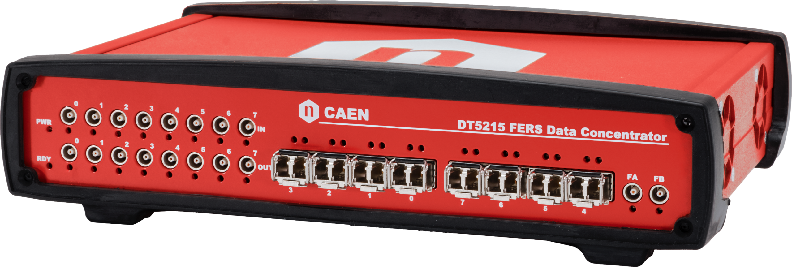
DT5215

DT5204
Request a Quote

Compare

|
Image
|
Name
|
Main Application
|
ASIC
|
No. of Channels
|
Communication Interface
|
Daisy chain full capability
|
|
|
DT5203 |
High resolution timing: ToA and ToT based analyses |
n. 1 CERN picoTDC |
64 |
MicroUSB, 10/100T Eth., TDlink |
1024 ch |
|
|
Coming Soon DT5205 |
PIN diodes, Silicon strips and GEMs readout: readout: PHA, Counting (MCS), high-resolution ToA and ToT based analyses |
n. 1 Weeroc Psiroc and CERN picoTDC |
64 |
MicroUSB, 10/100T Eth., TDLink |
1024 ch |
|
|
Coming Soon A5205 |
PIN diodes, Silicon strips and GEMs readout: readout: PHA, Counting (MCS), high-resolution ToA and ToT based analyses |
n. 1 Weeroc Psiroc and CERN picoTDC |
64 |
MicroUSB, 10/100T Eth., TDLink |
1024 ch |
|
|
DT5202 |
SiPM readout: PHA, Photon Counting |
n. 2 Weeroc Citiroc 1A |
64 |
MicroUSB, 10/100T Eth., TDLink |
1024 ch |
|
|
A5203 |
High resolution timing: ToA and ToT based analyses |
n. 1-2 CERN picoTDC |
64/128 |
MicroUSB, 10/100T Eth., TDlink |
1024/2048 ch |
|
|
A5202 |
SiPM readout: PHA, Photon Counting |
n. 2 Weeroc Citiroc 1A |
64 |
MicroUSB, 10/100T Eth., TDlink |
1024 ch |
|
|
Coming Soon A5204 |
SiPM readout: PHA, PSD, Photon Counting, high resolution ToA and ToT based analyses |
n. 1 Weeroc Radioroc and CERN picoTDC |
64 |
MicroUSB, 10/100T Eth., TDLink |
1024 ch |
|
|
Coming Soon DT5204 |
SiPM readout: PHA, PSD, Photon Counting, high resolution ToA and ToT based analyses |
n. 1 Weeroc Radioroc and CERN picoTDC |
64 |
MicroUSB, 10/100T Eth., TDLink |
1024 ch |
Technical Specifications
|
MECHANICAL |
|
||||||
|
TDC INPUT |
A5203: 64 channels (1 edge connector type HSEC8-170) A5203B: 128 channels (2 edge connectors type HSEC8-170)
|
||||||
|
TIMING RESOLUTION |
LSB = 3.125 ps
|
||||||
|
DYNAMIC RANGE |
Time measurement dynamic range in picoTDC:
Coarse time stamp in FPGA (56 bits @ 12.6 ns) con be combined with picoTDC data to extend the full scale range of the time measurement to a maximum dynamic of 64 bit (streaming acquisition mode). * 26bits (FSR = ∼ 210 μs) optional |
||||||
|
ACQUISITION MODES |
Common Start: TDC ch0 is the common start that opens the acquisition gate and represents the time reference. All other channels provide ΔT time measurements: TLEAD = ΔTN = TN – T0. The gate width is programmable by software. Any hit falling outside the gate will be discarded. Output Data: TLEAD or TLEAD + ToT Common Stop: Same as common start, but ch0 is used as a common stop that closes the acquisition gate: ΔTN = T0 – TN. Output Data: TLEAD or TLEAD + ToT Trigger Matching: The trigger signal (typ. from T0/T1 inputs) defines an acquisition window with programmable width and offset. All hits falling into the window will be recorded. Multi-hit acquisition is supported. All time measurements are referred to the Coarse Trigger Time Stamp (LSB = 25.6 ns), while the relative time between the hits keeps the TDC timing resolution (minimum LSB = 3.125 ps). Output Data: TLEAD or TLEAD+TTRAIL or TLEAD+ToT Streaming: Continuous hit recording, without any gate or trigger windowing. All hit time measurements are expressed as 64 bit time stamps (minimum LSB = 3.125 ps) and saved in the form of a sorted list. Output Data: TLEAD or TLEAD+TTRAIL (or TLEAD+ToT , COMING SOON) |
||||||
|
FPGA TRIGGER TIME STAMP |
|
||||||
|
FRONT PANEL I/0s |
Jumpers for IN-OUT bypass and termination removal (daisy chaining). Functions (SW programmable): Trigger, Acquisition Start/Stop, Sync, Busy, Veto, Signal inspection, etc … T0/T1 inputs can be used to drive TDC – Ch0 = Tref (possible degradation of the resolution because of the FPGA temperature dependence) |
||||||
|
FRONT PANEL LEDs |
|
||||||
|
INTERNAL PULSER |
Fast reduced-LVDS output (one signal only) with programmable frequency and width, for debug purposes |
||||||
|
COMMUNICATION INTERFACES |
|
||||||
|
FIRMWARE |
|
||||||
|
SOFTWARE |
Readout SW: Fully controlled by the Janus 5203 open source software for Windows® and Linux®. It can run in console mode (C program, with console commands and gnuplot display for plots) or connected to a GUI (Python) that implements user friendly configuration panels and run controls. Janus 5203 can acquire, plot and save output files with ToA, ToT histograms, as well as list files (trigger timestamp, ToA and ToT for each channel). Web Interface: Board information and monitoring, Ethernet configuration. |
||||||
|
ENVIRONMENTAL |
|
||||||
|
REGULATORY COMPLIANCE |
EMC: CE 2014/30/EU Electromagnetic compatibility Directive SAFETY: CE 2014/35/EU Low Voltage Directive |
||||||
|
POWER REQUIREMENTS |
Single power supply: +12 V. Accepted voltage range: MIN +7 V, MAX +15 V (110 V/220 V AC/DC converter provided with Desktop version only) |
||||||
|
POWER CONSUMPTIONS |
700 mA @ +12 V, i.e ∼ 8.4 W (A5203 – 64 channels) tbd (A5203B – 128 channels) |
Footer