

A1534
Obsolete
6 Channel Floating 8 kV, 200 µA Board
Features
- 6 independently controllable High Voltage channels
- 8 kV / 200 µA output range
- CPE 3P HV connectors
- Individual floating channels
- Low ripple
- Under/over-voltage alert, overcurrent and max. voltage protection
- Interlock logic for unit enable
- Software Tool for easy channel management

Overview
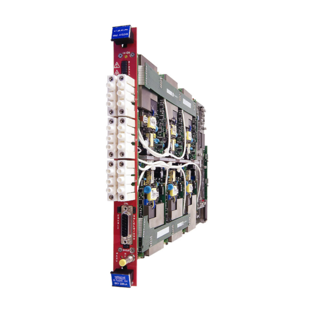
The CAEN Mod. A1534 is a single width (5 TE wide) board housing 6 HV floating channels equipped with CPE connectors. The channels feature independent returns, insulated up to 100 V between each other. The board is available with positive or negative polarity and is non-reversible. The output voltage range is 0÷8 kV (200 µA maximum output current) with 0.5 V monitor resolution.
| CPE 3P HV coaxial connector Double width (5 TE wide), 6 channel for Mod. A1534 |
Consult our connectors reference page for technical information.
If the output voltage differs from the programmed value by more than 3% of voltage full scale range, the channel is signalled to be either in OVERVOLTAGE or UNDERVOLTAGE condition. Moreover, for each channel, a voltage protection limit SVMAX can be fixed via software with 1 V resolution and the output voltage can not be programmed beyond this value. The HV RAMP-UP and RAMP-DOWN rates may be selected independently for each channel in the range 1÷500 V/s in 1 V/s steps.
The output current is monitored with 20 nA resolution; if a channel tries to draw a current larger than its programmed limit it is signalled to be in OVERCURRENT condition; the SY1527 system detects this state as a fault and reacts according to the setting of the TRIP parameter, namely:
1) TRIP = infinite ( = 1000 s)
When the set output current value is reached the channel behaves like a constant current generator.
2) TRIP = finite (< 1000 s)
The output current keeps the set value only for programmed time interval and then is switched off.
The TRIP time (i.e. the maximum time an OVERCURRENT condition is allowed to last) can be programmed in 0.1 s steps. The maximum output voltage (VMAX Hardware) can be fixed, through a potentiometer located on the front panel, at the same common value for all the board channels and this value can be read out via software. The boards host also a temperature sensor located on the PCB near the LV channels: the temperature values measured by this sensor are used to signal Over Temperature condition on the SY1527. The boards are provided with an “EN” input that disables the channels when it is not terminated.
Technical Specifications
- No. of Channels
6
- Output Voltage
0÷8 kV (connector output)
- Polarity
Floating
- Max. Output Current
200 µA
- Voltage Set Resolution
0.5 V
- Voltage Monitor Resolution
0.5 V
- Current Set Resolution
20 nA
- Current Monitor Resolution
20 nA
- VMAX hardware
0÷8 kV common to all board channels
- VMAX hardware accuracy
2% of FSR
- VMAX software
0÷8 kV selectable for each channel
- VMAX software resolution
1 V
- Voltage Ripple
<50 mVpp
- Ramp Up/Down
1÷500 V/s, 1 V/s step
- Vmon vs. Vout accuracy
typical: ± 0.1% ± 1 Vmax: ± 0.1% ± 2 V
- Vset Vs. Vmon accuracy
typical: ± 0.1% ± 1 Vmax: ± 0.1% ± 2 V
- Imon vs. Iout accuracy
typical: ± 2% ± 40 nA max: ± 2% ± 100 nA
- Iset vs. Imon accuracy
typical: ± 2% ± 40 nA max: ± 2% ± 100 nA
- Power consumption
60 W
Compare
Compare with High Voltage Power Supply.
Loading...
Accessories
- HV Cables
- High Voltage Cable Assemblies
Ordering Options
| Code | Description |
|---|---|
| WA1534XNAAAA | A1534N - SYx527 H.V. channels -8 KV 200 µA floating (6 ch) (Obsolete) RoHS |
| WA1534XPAAAA | A1534P - SYx527 H.V. channels +8 KV 200 µA floating (6 ch) (Obsolete) RoHS |