
Highlights
-
Complete detector readout system, designed for liquid
-
Easily customizable for a wide range of detectors
-
19” 4U crate housing 256 channels and the power supply
-
Plug-in Preamplifiers on hybrid circuits (sold separately)
-
12 bit / 2.5 MSps digitizing
-
1 or 8 Mbyte memory buffer
-
Independent channel self triggering
-
TT-Link: synchronization and trigger distribution over a single wire
-
FPGA based design: possibility of firmware customization
-
80MB/s Readout via daisy chainable optical link
-
Libraries, Demos (C and LabView) and Software tools for Windows and Linux
Overview
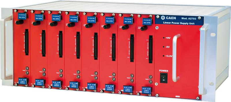
The CAEN Mod. SY2791 is a complete detector readout system, ideally suited for liquid Argon TPC (Time Projection Chamber), but easily customizable for a wide variety of detectors. The system is housed in a 19″ 4U crate that contains the A2793 AC/DC power supply unit and eight A2792 acquisition modules, with 32 channels each. In total, one SY2791 can read up to 256 channels.
The analog signals coming from the detector feed directly the inputs of the A2792s, where the preamplifiers (sold separately) are arranged in arrays of plug-in hybrid circuits (2 channels each) and enclosed in a metal shielded box. This solution allows the preamplifier to be chosen to match the specific requirements. The preamplifier outputs are digitized by 12 bit 2.5MS/s flash ADCs and processed by the internal acquisition logic, implemented in a programmable FPGA, which provides the trigger logic, the data storage in local memory buffers and the readout through a proprietary optical link, controlled by the PCI board A2818.
This compact and modular solution permits to place the readout electronics very close to the detector, giving the best performances in terms of noise and resolution. The optical fiber allows the system to be connected to the host PC as far as few hundred meters; the fiber guarantees easy cabling and absence of ground loops. One PCI card A2818 can control up to eight daisy chained A2792s (that is one full crate). Typically, one PC can host four A2818s, which means 1024 channels controlled and readout from a single commercial PC.
The system has been designed for the scalability: growing from a single crate with 256 channels up to experiments with thousands of channels is made easy by the TT-Link. This is a single wire bus (over a coaxial cable) connecting as many crates as needed, that distributes the same sampling clock to all the ADCs of the whole system and the same global commands, like triggers, start/stop acquisition, reset, etc. thus keeping all the acquisition boards synchronized.
Following the preamplifier output, the system operates as a waveform digitizer: the 32 serial outputs of the ADCs are connected to one FPGA which continuously picks the digital samples and stores them, in parallel for all the channels, into an array of circular memory buffers (Multi Event Buffer). When a channel is triggered, the FPGA keeps writing the programmable number of samples that stay within the post trigger window and then saves the current buffer (i.e. an acquisition window) of that channel; such data events are completed by a header and a time tag.
The acquisition can continue without dead-time in a new circular buffer. Channels operate independently from each other and are triggered when the relevant input signal crosses a programmable digital threshold. It is possible to propagate the trigger of one channel through the TT_Link and create channel groups in which one channel over threshold “alerts” the other ones that can decide to lower their threshold and let a very small signal trigger the acquisition. A global trigger common to all the channels can be also issued, using software commands or an external signal, regardless the threshold crossing.
The data throughput of the SY2791 is directly proportional to the sampling and trigger rates; in theory, it is possible to perform the acquisition of the analog signals in continuous mode. For this purpose, the system features an internal autotrigger, whose period is chosen in order to have concatenated acquisition windows and continuous waveform digitizing. However, the data throughput of this operating mode can exceed the maximum readout speed allowed by the bandwidth of the optical link. Algorithms for the zero suppression and/or data compression can be added to the firmware of the FPGA in order to reduce the amount of data to transfer. Future developments foresee on-line data processing for the extraction of the energy and/or the time of the digitized pulses in order to further reduce the data throughput.
CAEN provides a software package that contains the drivers for the PCI board A2818, the libraries (both in C and LabView) for optical link access and also some demos and examples of readout programs. Windows and Linux are both supported.
Developed in collaboration with ETH Zurich.
Request a Quote

Technical Specifications

|
Number of Channels |
32 for one A2792; 256 for the full crate. |
||
|
Preamplifier |
Plug-in hybrid circuits with two channels each (sold separately) |
||
|
Output Offset Adjust |
Two programmable 16 bit DACs (ch. [0:15] and [16:31]) for the DC offset adjust of the preamplifiers output. |
||
|
Test Pulse |
External from a double bridged LEMO. Internal with programmable voltage step (from 0.5 mV to 1V), positive or negative, shot control from TT-Link or SW command. |
||
|
ADC resolution |
12 bit (FSR = 3.3V, 1 LSB = 0.805 mV). Upgrade to 14 bit also available. |
||
|
Sampling frequency |
Programmable from ~40KHz to 2.5MHz. |
||
|
Memory |
1 MB (corresponding to 16K samples per channel). Expandable to 8 MB. |
||
|
Number of buffers |
From 2 (8K samples) to 1024 (16 samples) per channel. |
||
|
Trigger |
Independent trigger channel by channel (threshold crossing); global trigger for all the channels coming from the TT-Link, Control I/O connector or SW command. |
||
|
Trigger Time Stamp |
32 bit counter synchronous with the sampling clock. Range of 2147 sec. @ 2MS/s. |
||
|
Optical Link |
Daisy chainable from 1 to 8 A2792s. Maximum data throughput = 80MB/s. |
||
|
Power requirements |
|
Footer