

3 Years Warranty
3 Years Warranty

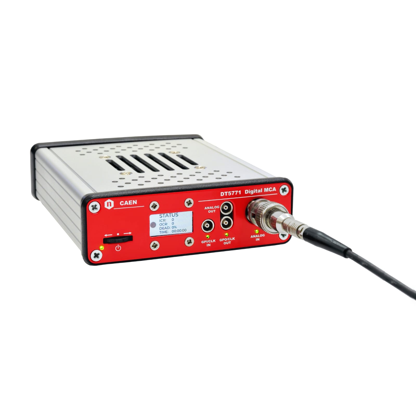
1 Channel Digital MCA
The DT5771 is a 64k Digital Multi-Channel Analyzer (MCA) designed for gamma spectroscopy applications, offering a 14-bit 200 Msps ADC, Ethernet and USB2 connectivity, and an intuitive web-based interface in a compact desktop form factor. It supports a wide range of detectors, including HPGe, silicon, and scintillation detectors (NaI, LaBr3), with variable gain, selectable 1 kΩ/50 Ω input termination, and AC/DC coupling for maximum compatibility.
The DT5771 supports multiple real-time acquisition modes:
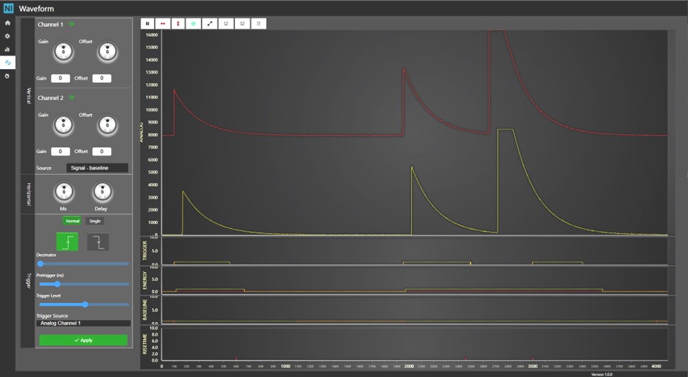
The web-based GUI provides intuitive control and real-time spectral analysis without additional software.
The module includes USB 2.0 and 1 Gbit Ethernet, GPIO for external triggers, and Clock/Sync I/O for multi-board synchronization. Status LEDs offer quick system diagnostics.
The DT5771 offers a user-friendly Web interface with Jupyter Lab for Python-based scripting
Seamlessly replacing the DT5770, the DT5771 enhances digital signal processing for gamma spectroscopy with next-generation performance.
Dimensions
Weight
Enclosure
Signal Processing:
CPU
MEMORY
ANALOG IN (front panel)
| Number of Inputs 1 |
| PREAMPLIFIER POWER SUPPLY (rear panel) | ANALOG OUT (front panel) |
|---|---|
|
|
| GPI (front panel) | GPO (front panel) |
|---|---|
|
|
POWER (front panel)
GPO (front panel)
| ANALOG IN (front panel)
GPI (front panel)
|
POWER/NAVIGATION SWITCH (front panel)
GRAPHIC DISPLAY (front panel)
ACQUISITION MODES
All the following information can be acquired simultaneously:
ANALOG INPUT SETTINGS
ANALOG OUTPUT SETTINGS
DIGITAL INPUT SETTINGS
DIGITAL OUTPUT SETTINGS
| PROCESSING SETTINGS
ACQUISITION SETTINGS
|
It is possible to save, load and download multiples configurations of all settings. Preset configurations stored on the device facilitates the parameters value assignment. Every time the settings are applied, the current configuration is automatically saved in order to reload the last settings value at power-on.
USB (rear panel)
| 10/100/1000T (rear panel)
|
OPERATING SUPPLY VOLTAGE
| POWER CONSUMPTION (Typ. @ +12 VDC)
|
The module can be powered by an external AC Power Adaptor included in the kit (+12 V, 3.75 A).
OPERATIONAL CONDITIONS
Compare with Multi Channel Analyzers.
Loading...
| Code | Description |
|---|---|
| WDT5771XAAAA | DT5771 - 1 Channel Digital MCA RoHS |
+39 0584 388 398
Contacts
What are you looking for?
Search