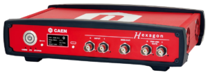
Hexagon
Digital MCA
Features
- Single and Dual 32k Digital MCA & Pulse Processor
- Fully supported by Quantus High Performance Quantitative Spectrometry Software
- Provides Pulse Height Analysis (PHA with MSS and coinc/antocoinc), Time-stamped Lists and Multichannel Scaling (MCS) modes
- Ideally suited for high resolution spectroscopy applications utilizing HPGe, CZT, Silicon, and scintillation detectors such as NaI and LaBr3
- Supports Resistive Feedback and Transistor Reset preamplifiers as well as PMT anode signals
- On-board SSD memory supports List and Spectrum data storage capability (up to 200,000+ spectra)
- Web interface for quick retrieval of board details, firmware upgrading, and output data file browsing
Overview
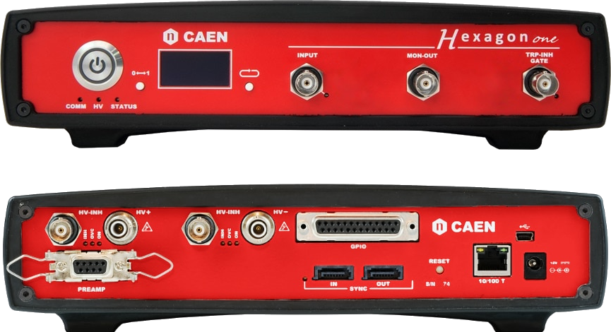
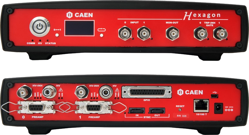
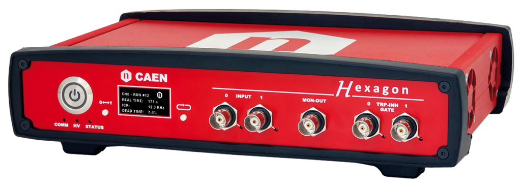
Hexagon is a stand-alone, single or dual digital 32k MCA, integrating input stage for the signal conditioning, fast analog-to-digital converter (ADC), digital processing algorithms, HV and Preamplifier Power Supply in a compact desktop form factor.
The instrument is suitable for high energy resolution semiconductor detectors, such as HPGe and Silicon detectors, for CZT, but also for scintillation detectors as Nal and LaBr3. It can manage positive and negative signals from resistive feedback or transistor reset preamplifier detectors; additionally accepts signals coming from PMT anodes.
Operating Modes
Hexagon can be configured to operate in Pulse Height Analysis (PHA) acquisition mode, in Multichannel Scaling (MCS) acquisition mode, or in both PHA and MCS modes simultaneously. Multiple PHA spectra can be collected using Multispectral Scaling (MSS) mode with no data loss when switching to a new spectrum. The Time-Stamped List mode permits time and energy events to be saved either to on-board memory or to the host PC for offline analysis and post-processing. Analog input signals and internal digital filter outputs can be inspected via the Signal Inspector mode. Additionally, Compton/AntiCompton data acquisition is supported by taking advantage of the 2-input channel version.
I/O Equipment and Additional Features
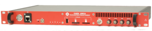
Hexagon is equipped with I/O connectors which support several features beyond the standard MCA functionality. A DB25 I/O connector supports PHA Start/Stop, SCA, MCS, Coincidence/AntiCoincidence, Acquisition Start/Stop, ICR, Run Status, Sample Changer, and Sample Ready signals. The BNC connectors are reserved for Transistor Reset Preamp (TRP) inhibit, where the inhibit takes place on an external digital signal and can be extended in time via programming. Two SATA connectors allow for very precise multi-board synchronization, time stamp alignment, and system building via a simple daisy chain. Front Panel LED indicators inform the user as to board and I/O status, polarity of the power supply, and multi-board sync status. An OLED display provides general board information, real-time statistics on ICR, OCR, Real/Live/Dead Time, as well as details on the HVPS channel output.
HV and LV Power Supply
Hexagon can provide HV bias for up to two detectors. Three ranges of bias voltage and current, which are software configurable on a per-channel basis and hardware protected, allow the user to tailor the output V/I to specific detector types such as PMT (2 kV / 1 mA), HPGe (5 kV / 30 μA), and Silicon (500 V / 50 μA). The 2-input channel version of Hexagon allows the user to select the polarity configuration upon ordering: Positive-Positive, Negative-Negative, or Mixed. The 1-input channel version of Hexagon is provided with an HVPS configuration which includes 1-channel Positive Polarity and 1 -channel Negative Polarity. HV inhibit is supported with both positive and negative polarity. Hexagon also integrates low voltage outputs (±12 V / 100 mA and ±24 V / 50 mA) to power preamplifiers. Detector Temperature and Nitrogen Levels may be monitored via external sensor interface.
Software
Hexagon is controlled by Quantus, a general-purpose gamma-ray quantitative spectroscopy software. Independently of the detector geometry or sample used, Quantus can analyze any recorded gamma-ray spectrum for radionuclide identification and quantification. Multiple spectra can be analyzed at the same time, and/or acquiring data from several connected detectors is supported. The advanced Graphical User Interface incorporates tools for a wide set of necessary analysis functions: peak searching, peaks continuum subtraction, peak qualification, automatic ROI location, energy calibration with visual interaction, FWHM calibration, efficiency calibration, nuclide identification and activity calculation.
Hexagon keeps the compatibility with MC2Analyzer (MC2A), CAEN multi-board configuration and data acquisition software with basical spectrum analysis (ROI, energy calibration, FWHM, statistics), supporting all CAEN MCAs and digitizers running the DPP-PHA algorithm.
The embedded Linux-based ARM processor makes Hexagon well suited for unattended operations. Taking advantage of the available SDK tool, the user can customize the software (running embedded or on an external PC). The parameters of the processing algorithms can be tuned according to the detector or the application, and custom routines can be developed for automated operations, such as on-board spectrum and list recording, acquisition settings, logging and autonomous data acquisition when unconnected from external hosts.
Connectivity
Hexagon can be controlled with a point-to-point direct connection through the USB 2.0 link and with a remote network connection by the Ethernet 10/100T port. The module also features a web interface that supports basic operations (sans spectroscopy software) by simply opening a web browser. The web interface is a quick and useful tool for finding basic board information (e.g. model type, serial number, firmware version, CPU load averages, real memory occupancy), for retrieving files saved on the onboard memory, for setting operational functions for each run (e.g. order, cut, copy/paste files, create and delete directories, user rights, etc.), and for managing network settings and upgrading firmware.
Technical Specifications
- Performance
SIGNAL PROCESSING
– Throughput tested up to 200 kcps
– Integral Non-Linearity (INL) 0.05% over the 99% of the full-scale range for Coarse Gain < 8; 0.1% for higher gains
– Differential Non-Linearity (DNL) < ±1% over the 99% of the full-scale range
– Dynamics down to 4 keV @ 3 MeV FSR (noise peak at the same height of Compton); measured with 7229P HPGe Canberra detector
– Pile-up Rejection and Live Time Correction; Pulse Pair Resolution: < 0.5 μs typical (depending on the fast discriminator shaping time)
– Dead-Time Correction error < 5% on the net area of a static reference source offended by a variable rate source ranging from 1 to 100 Kcps (at fixed Live Time Preset)
– Resolution best result is 0.61 keV @ 122 keV, 1.63 keV @ 1332 keV, measured with Cryo-Pulse 5 Plus Electrically Refrigerated Cryostat HPGe Canberra detector, equipped with iPa Preamp
- On-board CPU and Logging
CPU
– 1 ARM Cortex-A8 1 GHz (SDRAM Memory 512 MB DDR3L 800 MHz) running Linux Debian system
– The embedded CPU is accessible for compiling customized routines and implementing unattended and automated operations by the provided SDK; 2 GB of space available for user installationsSSD Memory
– 32-GB microSD card, non-detachable; logging capability more than 200.000 spectra
- Inputs
INPUT (front panel)
– Analog signal input connector; one unit in Hexagon single-input version; BNC type
– Accepts positive or negative signals from PMT anode or both Resistive Feedback and Transistor Reset detector preamplifier; 500 Ω input impedance.
– AC or DC coupling selectable by register with 5 μs, 11 μs or 33 μs possible value for the AC time constant; input range is 1 Vpp divided by the selected gain, 4 Vpp with x0.25 or 2 Vpp with x0.5 attenuation activated.
HV INH (rear panel)
– High voltage inhibit connector; two units; BNC type.
– Inhibit function is duplicated on the rear PREAMP connector; DB9 type.
– Polarity of the HV INH signal is software selectable
Positive polarity (default):
the enable condition (cold detector) is an open circuit or active high, which means +2 V to + 24 V; inhibit condition (warm detector) is ground or active low, that is -24 V to -2 V
Negative polarity:
the enable condition (cold detector) is ground or active low, which means -24 V to -2 V; inhibit condition (warm detector) is an open circuit or active high, that is +2 V to + 24 V
TRP INH / GATE (front panel)
– Transistor Reset Preamp/Gate Input connector; two units; BNC type; software selectable compatible logic TTL or NIM and function:– TRP-INH:Transistor Reset Preamplifier Inhibit; the inhibit time value is determined by the longer of two conditions: either by the duration of the external signal or by the duration of an internal inhibit timer (maximum value is programmable up to 160 ms); signal processing is halted during the inhibit time.
– GATE: Input signal acts as gate for coincidence/anticoincidence acquisition mode; event storage can be allowed/vetoed for the duration of the gate signal or for a programmable fixed time; programmable time ranges from 0.01 μs to 160 ms.DC POWER IN (rear panel)
– 12V DC power jack; mechanically lockable for a safe connection;
– Imax: 2.5 A.
– AC Adaptor (12 V, 3.75 A) included in the kit.
- Outputs
HV (rear panel)
– Detector High Voltage power supply output connector; two units; SHV type.
– Software selectable Voltage/Current output range options:– 20 V to 2000 V @ 1 mA, suited for PMTs.
– 20 V to 5000 V @ 30 μA, suited for HPGe detectors.
– 20 V to 500 V @ 50 μA, suited for Silicon detectors.– Ripple < 5 mVpp @ 2 kV < 10 mVpp @ 5 kV
– Voltage / Current range may be configured in the software on a per-channel basis, so that the user can simultaneously bias identical or separate detector types (PMT, HPGE, Silicon) with a single Hexagon module.
– HVPS Polarity Output is selectable upon ordering (Positive-Positive, Positive Negative, Negative-Negative); the single-input version of Hexagon includes Mixed (Positive-Negative) HVPS output.
– Front Panel Polarity LED identifies positive or negative output for each channel by colour.PREAMP (real panel)
– Preamplifier power supply output connector; two units; DB9 type.
– Two power rails: ±12 V (± 2%) @ 100 mA ±24 V (± 2%) @ 50 mA.
– Ripple < 5 mVpp– Includes pins for 0 ÷ +10 Vdc level output, for detector temperature (PT100/PT1000 compliant) or Nitrogen level sensor readout, and for HVPS external inhibit input (in OR with HV INH connector; BNC type).
MON-OUT (front panel)
– Analog output; BNC type
– Provides a selection (software selectable) of internal analog probes:
A copy of the input signal (4 Vpp FSR)- The Trapezoid
- The Trapezoid-Baseline
- The Fast Trigger
- General Purpose I/Os
GPIO (rear panel)
– Connector for TTL I/Os; one unit; DB25 type (adapter to BNC available on request).
– Inputs (LVTTL, Zin 1 kΩ):– Trigger Time Stamp Reset:External reset of the time stamp counter; minimum pulse width 15 ns; software programmable polarity.
– Acquisition Start/Stop: External Acquisition Start/Stop signal; minimum pulse width 15 ns; software programmable polarity; software programmable as edge sensitive (starts on first pulse and stops on second pulse) or level sensitive (starts on active signal and stops on inactive signal).
– External Trigger: External Trigger signal; minimum pulse width 15 ns; software programmable polarity; can be either a trigger for the channel or a trigger validation incase of acquisition in Coincidence mode.
– MCS Channel Advance: External Multichannel Scaler Channel Advance signal; minimum pulse width 15 ns; software programmable polarity; MCS channel advances upon external pulse.
– MCS Sweep Advance: External Multichannel Scaler Sweep Advance signal; minimum pulse width 15 ns; software programmable polarity; the sweep currently in progress can be reset by external pulse.
– Sample Ready: Sample Ready signal; minimum pulse width 15 ns; software programmable polarity; acquisition begins on an inactive signal, while an active signal delays the start of acquisition.– Outputs (LVTTL, do not require 50 Ω termination):
– ICR: Incoming Count Rate; generates a positive pulse 150 ns wide at each event acquisition.
– SCA: Single Channel Analyzer; output pulse width 150 ns; software programmable polarity; a pulse is generated for each event whose energy stays between the Upper and Lower Level Discriminators (ULD, LLD).
– Sample Changer: Sample Changer signal; pulse width 140 ms; software programmable polarity; a pulse is generated for each sample advance command received by the instrument.
- LED Indicators
Front Panel LEDs
– COMM: communication LED; colour green; turns on in case of activity over the USB or the ETHERNET channel.
– STATUS: Status LED; bi-colour red/green:– Continuous green: the board is ready to start.
– Blinking green: the board is in RUN state.
– Continuous red: the board is in BUSY state.– HV: HVPS LED; red colour; turns on in event of an HV fail condition.
– INPUT: Trigger LED; colour green; turns on when a trigger is generated on the associated analog input channel.
– TRP-INH/GATE: Transistor Reset Preamplifier inhibit LED; colour green; turns on when the inhibit is active on the associated TRP input channel.
Rear Panel LEDs
– INH: HVPS channel inhibit LED; colour red; turns on when inhibit is active.
– OVC: HVPS channel over-current LED; colour red; turns on if the channel tries to draw more current than the programmed limit.
– ON: HVPS channel enable LED; colour red; turns on when the HVPS channel is active.
– POS: HVPS positive polarity LED; colour green; turns on in case of positive HVPS channel.
– NEG: HVPS negative polarity LED; colour yellow; turns on in case of negative HVPS channel.
– SYNC: Synchronization LED; colour green; turns on when the clock of the board is locked with the clock signal on SYNC IN.
- Acquisition Modes
All settings are saved while the module is in power-off state; last configuration is automatically reloaded at power-on.
– Signal Inspection: The analog input and the outputs of the digital filters can be inspected and plotted to optimize the algorithm parameters to attain the best possible spectrum. Waveform data dump available with Quantus. The incoming rate is limited by the record length and communication link.– PHA: By way of setting the programmable digital pulse processing parameters, the board will develop energy histograms that may be plotted and saved to file; spectrum can be binned at a configurable number of channels by the Conversion Gain control.
– MSS: Multispectral Scaling collects multiple PHA spectra; supports software or external TTL input Spectrum Advance command; not affected by dead-time while switching to a new spectrum.
– Coincidence/Anticoincidence: configurable either for coincidence and anticoincidence between the board analog inputs (IN 0 and IN 1), or for external coincidence (GATE) and external anticoincidence (INH).– Time-Stamped List: Raw energy and time tag data are provided and can be saved to file; 62-bit time tag counter; resolution of 10 ns; roll-over tracking event.
– MCS:Multichannel Scaler mode; counts on fast discriminator, SCA or external inputs; the Start/Stop, the Channel Advance and the Sweep Advance can be on software command or on external signal (GPIO connector).
– Unattended: Local storage of lists and spectra on the internal microSD memory without need of external PC control.
- Controls
GAIN
– Through a combination of coarse and fine gain, the overall gain can be continuously adjusted from x0.8 up to x563.2 with respect to the 1 Vpp input range:– Coarse Gain: x1, x2, x4, x8, x16, x32, x64, x128, x256
– Fine Gain: from x0.8 up to x2.2 in steps of 0.001– By selecting the gain attenuation, the input range can be extended to 2 Vpp or 4 Vpp preventing saturation conditions, particularly for preamp signals with large DC offsets or transistor reset preamplifiers with a large output ramp dynamic range:
– Gain Attenuation: x0.25, x0.5
– Configuring the conversion gain defines the number of channels for the acquired spectrum:
– Conversion Gain: 256, 512, 1024, 2048, 4096, 8192, 16384, 32768 channels
DC Offset
The DC offset of the analog input is adjustable in the whole input range
Algorithm
– Input Signal
Pulse Polarity: NEGATIVE or POSITIVE input polarity selection
– Trapezoid Filter: serves for energy calculation; Trapezoid, Trapezoid-Baseline and Peaking signals can be displayed in Signal Inspection mode
– Rise Time: trapezoid rise time corresponds to the shaping time of the traditional analog chain; configurable values between 0.02 μs and 37 μs
– Flat Top: the flat region of the trapezoid, in which the energy is calculated; configurable values between 0.02 μs and 3 μs
– Peak Delay: adjusts the point of the flat top where the energy value is calculated; the peaking (peak position) signal can be displayed in Signal Inspection mode; configurable values between 0% and 100%
–PUR Protection Time: starts at the end of the flat top; plays a role in the pile-up rejection; configurable values between 0 μs and 81.84 μs– Pole/Zero Compensation: exponential decay time fine adjustment to avoid trapezoid overshoot or undershoot for a correct evaluation of the energy value:
– Decay Time: manually and automatically configurable between 0.1 μs and 650 μs
– Baseline Restorer: operates on the trapezoidal filter output to calculate the baseline by averaging a programmable number of points before the start of the trapezoid.
– Fast, Medium, Slow: manual setting of the baseline restorer to a fixed rate
– Fast Discriminator: applies to time tagging and ICR; based on double triangular filter; manual and automatic setting of the threshold; time stamp resolution of 10 ns, 62-bit counter; trigger signal can be displayed in Signal Inspection mode.
– Fast TRG Shaping: configurable values between 0.01 μs and 0.8 μs
– Coupling & TRP: DC/AC coupling selection and Transistor Reset settings
– Coupling: DC coupling option for Charge Sensitive Preamplifiers; AC coupling option for Resistive Feedback and Transistor Reset Preamplifier with three selectable shaping constants: 5 μs, 11 μs and 33 μs (the trapezoid Decay Time must then be set accordingly.
– Reset Length: inhibit time due to the reset discharge (AC coupling); applies to the Transistor Reset Preamplifier.
– Pole Zero (%): analog pole zero compensation in case of Resistive Feedback Preamplifier (AC coupling)– MCS:
– Dwell Time: 1 µs up to 4000 µs with resolution of 1µs
- ADC
- RESOLUTION
16 bitsSAMPLING RATE
100 MS/s
- Synchronization
SYNC IN (rear panel)
– Input connector for the synchronization of multiple Hexagon boards; one unit; SATA type
– Clock sync, time tag reset and list marker functions; daisy chainable to multiple boards in combination with SYNC OUTSYNC OUT (rear panel)
– Output connector for the synchronization of multiple Hexagon boards; one unit; SATA type
– Daisy chainable to multiple boards in combination with SYNC IN
- Active Buttons
POWER (front panel)
– Power on/off button; blue illuminated when the power is onRESET (rear panel)
– Holding this button down for 3 seconds causes a global reset of the board (i.e. HVPS channels ramp-down and board resets)
- Communication Interfaces
USB (rear panel)
USB connector; USB 2.0 compliant; type mini-A.
When connecting Hexagon to a host PC for the first time, the driver is automatically installed and is immediately recognized by the operating system(Windows® and Linux™), identifying the unit as an external storage device containing documentation and software.
USB cable included in the kit.10/100 T (rear panel)
– Ethernet female connector; RJ-45 type.
– Supports 10 or 100 Mbit/s connection to a PC or ETH hub.
– FTP cable included in the kit.
- Monitoring Display
GRAPHIC DISPLAY (front panel)
– Monochrome 1.3ʺ OLED display only for monitoring usage.
– Screen 1: Time acquisition data– Real Time [hh mm ss] / Live Time [hh mm ss] / Dead Time [%]
– Screen 2: Readout data.
– ICR [Hz], [kHz], [MHz] / OCR [Hz], [kHz], [MHz] / Dead Time [%]
– Screen 3: HVPS data.
– Vmon / Vset [V] / Imon[μA]
– Screen 4: Network addresses
– ETH / USB e1.e2.e3.e4 u1.u2.u3.u4; (ETH IP); (USB IP).
– Screen 5: Board Information
– Model: DT500xx; Serial Number; Firmware version.
BROWSE BUTTONS (front panel)
– Channel select (0<—>1): switches between the two analog input channels (if Screen1 and Screen 2) or the two HPVS channels (if Screen 3).
-Screen Select Button: scrolls through the screen options
- Mechanical
- Enclosure
Aluminium with durable rubber front and rear supports
Size
262 W x 66.2 H x 195 L mm³ (including connectors) 262 W x 66.2 H x 171.6 L mm³ (without connectors)Weight
1400 g.
- Firmware
UPDATES
– Firmware updates are available for free download on CAEN website: www.caen.itUPGRADE
– Firmware can be upgraded via USB/ETHERNET through the Web Interface.

- Documentation
- Software
- Firmware
Firmware
Data Sheet
Manuals
Middleware
Application SW
Guides
Brochures, Flyers
Application Notes
Related Software Products
Compare
Compare with Multi Channel Analyzers.
Loading...
Ordering Options
Code | Description |
---|---|
WDT5000XMAAA | DT5000M - HEXAGON Dual Dig. MCA - 1 HVPS +5kV/30uA, 1 HVPS -5kV/30uA, 2 LVPS ±12V/100mA, ±24V/50mA RoHS |
WDT5000XNAAA | DT5000N - HEXAGON Dual Dig. MCA - 2 HVPS -5kV/30uA, 2LVPS +/-12V/100mA, +/-24V/50mA RoHS |
WDT5000XPAAA | DT5000P - HEXAGON Dual Dig. MCA - 2 HVPS +5kV/30uA, 2LVPS +/-12V/100mA, +/-24V/50mA RoHS |
WDT5001XMAAA | DT5001M - HEXAGON-one Dig. MCA - 1 HVPS +5kV/30uA, 1 HVPS -5kV/30uA, 1 LVPS ±12V/100mA, ±24V/50mA RoHS |